A Teensy/Arduino AD9834 Based WSPR Transmitter
The Weak Signal Propagation Reporting (WSPR) protocol is designed to allow for radio propagation conditions to be measured across different frequencies and times. It is a slow speed digital mode, and there exists a network of thousands of receiving stations worldwide reporting the identity of received stations, along with their locations, to a central server. Whilst there are applications of this in the field of propagation condition reporting, the fact that there are many receivers always available and logging received signals in real-time, and that the protocol is slow speed and simple to implement, coupled with the fact that signals can typically propagate huge distances, makes this an exciting protocol to build your own transmitters for and see impressive results immediately.
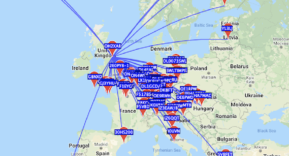
The map above shows the stations receiving a single message sent on a December evening from the North East of England using a simple wire antenna and about 2.5 watts of power.
Using the the AD9834 DDS IC along with a Teensy (or Arduino) micro-controller, it’s possible to build a flexible WSPR transmitter. Here are some construction notes along with code snippets and repositories for implementing this.
Overview
The system is conceptually quite simple. Time and location are sampled from a GPS receiver. One second before the start of a transmission, the WSPR message is created and the symbols encoded. An interrupt timer then advances through the symbols, where a Look up Table (LUT) matches the symbol value (0-3) to the corresponding value to be written to the FSelect register of the AD9834.
The Maidenhead Grid Locator is calculated dynamically from the GPS location. Power Level, Callsign and band are hardcoded but could easily be changed dynamically. The RF path consists of a buffer to lower the output impedance and raise the voltage of the signal from the AD9834, and a 5W Amplifier Kit from QRP Labs along with the corresponding LPF. The output from the driver circuit is relatively low, and so the power supplied to the antenna from the PA is around 2.5W. I also had trouble with the driver circuit outputting a good signal at 14Mhz (20m) - so this has only succeeded on the 7Mhz (40m) band.
The above map shows the reported spots on an evening in December on the 40M band, operating from the North East of England. The antenna was an ATU-tuned random-wire antenna hung from the roof of a small house to a tree.
Shown below is a system / circuit diagram of the transmitter. Not shown is the ATU and LPF. The PA is a 5W HF PA Kit from QRP Labs, with the standalone raised cosine controller add-on, and the LPF is a 40M filter also from QRP Labs. I’ve been impressed with these kits and am looking forward to using them in further projects.
I added a simple OLED Monochrome display from Adafruit to indicate when a GPS Fix is available, and to show the current time and transmission state. I’d wager that most of the code and processing power is spent on driving this!

The code for the entire project is here. It is not intended to be a ’turn-key’ solution, particularly complete, or tidy. My board and layout was one I’d been experimenting with for a while so more efficient pin choices etc. would likely be possible. It’s designed to be used with the Arduino API and libraries but outside of the API by using a Makefile. I would like to look into eliminating the need for the Arduino API in the future.
Controlling the AD9834
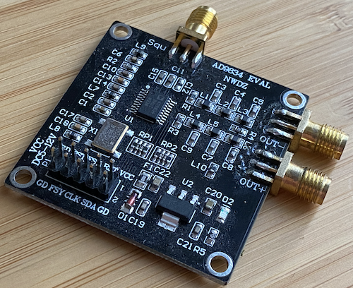
The AD9834 is controlled over a SPI interface. Breakout / evaluation boards are available cheaply on AliExpress and Amazon for this device, but of course it’s not possible to guarantee that they’re genuine.
The device has two frequency registers, and when changing frequency care must be taken to not write to the one currently in use. Data is written in 16 bits at a time, and usually consists of a control register followed by data. In the case of frequency data the data is two 16bit bytes wide, consisting of a Most Significant and Least Significant Byte. I wrote an extremely minimal arduino-style library for doing this - here - after figuring out the necessary SPI configurations from the datasheet and a bus analyser.
The formula for determining the Frequency (F) to Register Values is:
F x 228 / 75000000
Where 75000000 is the (standard) clock frequency of the AD9834.
Given that for this purpose, we know the exact frequencies we wish to repeatedly transmit at, and that they are a finite set (4 symbols) - it makes sense to pre-calculate these values and store them as part of the program as opposed to performing floating point division repeatedly (particularly seeing as this application is time sensitive). I noticed that on my board there was some frequency drift, and that there is a risk of the signal falling outside of the WSPR frequency. Whilst it’d still be well within the amateur band, I found that the decoder software on listening stations would ignore it - so I usually chose base frequencies somewhere within the centre of the WSPR Frequencies. This code will produce the correct register values for the various symbol frequencies:
Buffering the Signal
The AD9834 is usually configured as a current source into a 200Ω load, giving it effectively a 200Ω output impedance. At ~7MHz, even into a 1MΩ input impdance (the scope) the voltage from the output is low, at around 146mV RMS. Into 50Ω this would give a 47mV RMS:
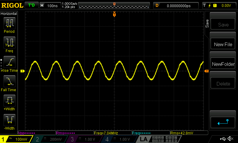
This is clearly far too low to drive anything useful (although I have been able to use it to drive active mixers, such as the AD831 directly). The circuit for the buffer, shown above and based on this design both raises the voltage, and will also drive a lower impedance - with a level to around 1V RMS into 50 Ohms:
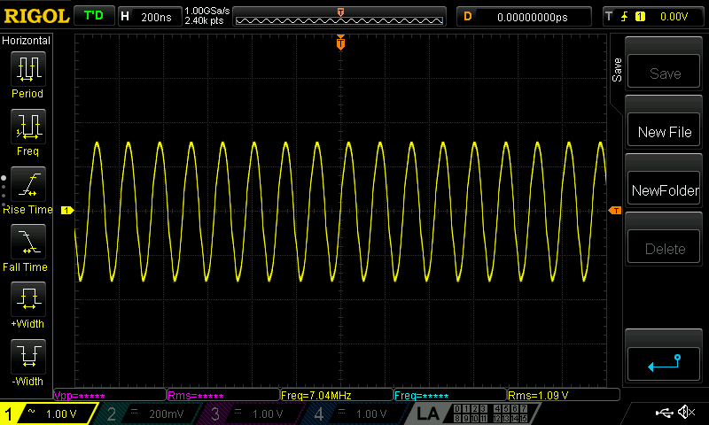
We can however see that there is some distortion introduced, although it is still relatively clean:
Unfortunately, I was unable to get this same circuit to perform adequately at higher frequencies (14MHz).
This level was sufficient to produce around 2.5W output from the PA.
WSPR Encoding
The WSPR protocol is open source, although the reference implementation (WSJT-X) is written in fortran. I found it convenient enough to adjust this implementation to print out extra debug information and test parts of it in isolation, but I did not wish to try and build it for the teensy/arduino as part of this project. An excellent overview of the encoding process however is given by G4JNT here, and from this document I was able to create a standalone implementation in C++, along with robust unit tests. This is a project I plan on expanding and improving over time. The algorithm for determining the Maidenhead Grid locator is simple and implemented as a single header as part of the main code project.
Timing & Location
The timing of the system is driven by a cheap GPS module - in this case a GoouuuTech GT-U7 based board. I had to search a little to find a device with a PPS output but this seems to work very well. It is quite amazing really that for around $5 it’s possible to get a device that’ll accurately (enough for this at least) give you your location, and time, anywhere in the world and with less than a minute time to fix!
There are many libraries available to parse the NMEA data from the GPS into a Lat/Long and Date/Time (and more) structure for you. I picked NeoGPS. In general I tried to write the software to be as asynchronous as possible, with hardware interrupts setting flags to be checked in the main loop, and nothing delayed or polled. However it does appear to be that we must poll the serial port in a loop in order to parse the data. I found that reading the serial port at intervals did not work reliably with this library - but I have not investigated the use of any Serial interrupts (if they’re available) or more advanced techniques.
For timing, the software periodically updates the Teensy’s RTC with the GPS value, and it is this RTC that drives the transmission timings.
When it is time to transmit, a timer interrupt is started that advances a pointer to next symbol’s frequency value and triggers a write of this to the (not currently in use) AD9834 Frequency register (followed by control register write to switch over to using the new register).
Conclusions & Next steps…
This is far from a ‘feature complete’ general WSPR transmitter (such as is available as a kit from QRP Labs) however it proved some interesting points:
- The AD9834 is a capable device that can drive a PA fairly easily with extra circuitry. The ability to output a pure sine wave and control the Frequency and Phase during transmission means that more advanced modulation techniques are certainly achievable.
- The output level is however very low, it cannot be used as a VFO without a suitable buffer / amplifier
- Pairing it with a high-speed op-amp might be a better approach for use at higher frequencies
- The WSPR encoding process is very lightweight, although consists of several stages.
- Next steps would be the implementation of ’type 2’ messages - such as compound callsigns
As always, a good antenna and tuner will help immensely - I am however pleased with the results of this with a very simple antenna - with being able to consistently reach much of Europe from the location in the UK.